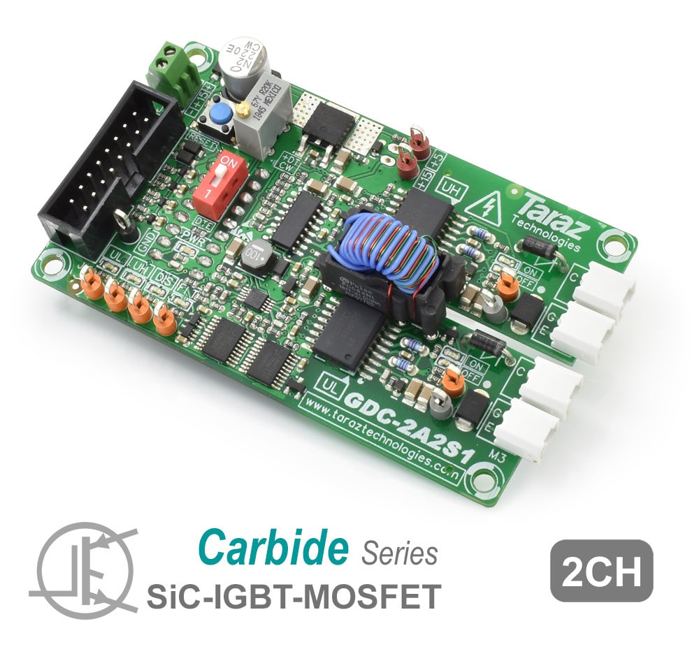
2 Channel SiC Gate Driver Board
GDC-2A2S1
Applications
✓ 2 Switch Isolated SiC/IGBT/MOSFET Gate Driver
✓ DC-DC Converters
✓ Switched Mode Power Supplies
✓ PFC Rectifiers
Features
✓ Suitable for 1200V SiCs, IGBTs & MOSFETs up-to 120A
✓ 110ns propagation delay, 100KV/us CMR
✓ Short circuit protection with soft shutdown
✓ Active miller and output UVLO protection
✓ 1200 Vdc working voltage with 3 KVac isolation
✓ Configurable dead-time, PWM/Indep. inputs
✓ Fault feedback and fault latch protection
Specifications
| Parameter | Value | Unit | Parameter | Value | Unit |
|---|---|---|---|---|---|
| Output Channels | 2 | – | Output Voltage | +20/-5. +18/0, +15/0, +15/-5, +15/-15 | V |
| Peak Output Current | 2 | A | Avg. Output Power per Channel | 1000 | mW |
| Input to Output Isolation | 3000 | Vac | Max. Working Insulation Voltage | 1200 | V |
| Max. Propagation Delay | 110 | ns | Min. Common Mode Rejection (CMR) | 100 | kV/us |
| Operating Temperature | -25 to +70 | °C | Active Miller Clamp Current | 1.6 | A |
| Input Modes | Configurable PWM / Dual | – | Dead-Time | User Adjustable | – |
* Note 1: All ratings are given at Vs=15V and 25°C ambient temperature unless otherwise specified.
FAQs
How to choose gate resistance for my application?
Selecting the right value of the external gate resistance is essential in limiting the noise and energy loses in the switching operation and it’s selection may vary depending on the transistor being used. The data sheet of the transistor IC shows recorded test values of operation under optimal condition which also includes the value of external gate resistance (RGATE) which enables switching while minimizing turn on (Eon) and turn off (EOFF) loses.
How to select gate driver output voltage?
The optimal value of gate driver output voltage depends on the switch being used. Usually SiC FETs come in multiple recommended voltages such as +20/-5V, +18/0V and +15/-5V. You can find more information in Absolute Maximum Ratings table in switch datasheet.
What is the difference between IGBT & SiC gate driver?
SiC gate drivers have higher common mode rejection and low propagation delay as compared to IGBT gate drivers, making them suitable for higher speed applications while, at the same time, having all the advanced protection features.
How can I connect these gate driver boards to my circuit?
Each output channel of the gate driver board has a male plug connector which can be directly connected to the gate-source/emitter terminal with the selected gate resistance to provide with the required gate voltage for the switching operation.


